links → HOME, chapter 1, chapter 2, chapter 4, chapter 5 and 6, chapter 7, chapter 8
A sextant is nothing more than a precise optical angle measuring instrument. The navigator needs it to measure the angle of elevation between the horizon and the centre of a celestial body to within fractions of a minute of arc. The aim of this measurement is to determine the distance between an observer’s position and the place on Earth where the observed celestial body is currently at its zenith. Depending on the skill of the navigator and the precision of the instrument, this distance can be determined with an accuracy of up to 500 metres. However, this accuracy is no longer achievable even in the slightest sea state.
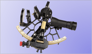
3.1 Construction of a sextant
The basic construction of a sextant is shown in Figure 3.1. Its main components are the frame with degree arch and handle, the swivelling alidade and the telescope. The mirrors and numerous shadow glasses are also conspicuous. It is therefore a very impressive instrument. On board, the sextant is kept in a sturdy wooden box – usually made of mELogany – into which it should be returned after each measurement. This box should be attached as firmly as possible to an easily accessible place on a wall. The box contains other accessories for the care of the instrument. The case should be designed in such a way that the sextant can be stored in it how in use, i.e. without having to fold back all the shadow glasses first.

The handle is usually made of wood and is firmly attached to the frame. In the handle there is usually also a space for a battery for illumination, so that the angle can also be read in the twilight.
The frame or body of a sextant is classically made of bronze or brass. A material that is widely used today is aluminium because it is light. However, bronze is still used for very high-quality instruments. The colour of the frame is usually black. White lacquered sextants have the advantage that they cannot heat up too much during prolonged exposure to sunlight. This also prevents the frame from warping, which is good for measuring accuracy. Sextants are built with tolerances of 1/1000 mm. Any unnecessary heating in the blazing sun and any impact can affect the measuring accuracy. For some time now, sextants have also been made of plastic. Glass-fibre reinforced plastics are used. They are very light and can therefore even be sensitive to wind.
The limbus is the degree arc with the angle scale. This is applied to the frame. The scale covers an angular range of at least 120 degrees. Angles below zero degrees must also be measurable, for example, in order to detect a negative index error. The uniformity of the scale and its clarity give a first impression of the instrument. After all, the distance between two graduation marks, which is just over 1 mm, embodies a distance of 60 nautical miles on the earth’s surface.
The alidade is the moving arm of the instrument. At the pivot point of the alhidade is the index mirror and at the lower end is the micrometer drum or vernier. To move the alhidade, its clamp must be loosened. The alhidade must be easy to move, leaving a distinctly stable impression. With plastic sextants, the alhidade tends to be subject to static friction. If this is the case, it will not glide but jump in stages. A little Vaseline can remedy this.
The drum allows fine adjustment and moves the alhidade one degree further with each revolution. The graduation on the drum therefore goes from 0 to 60 minutes of arc. A fixed vernier allows the reading of fractions of a minute of arc, which is unlikely to be of much practical use on smaller vessels. Anyone who can achieve an accuracy of two minutes of arc in a swell can call himself an expert, because that is an inaccuracy of two nautical miles. With precision sextants, the setting accuracy even reaches ten arc seconds, which is then a few hundred metres more or less in the distance to the image point.
Even plastic sextants have an adjustment accuracy of 20 arc seconds, but adjustment accuracies are not identical to measurement accuracies. Cheap plastic sextants have no drum, but only a vernier, which is supposed to give a setting accuracy of one minute of arc. That would be one nautical mile. An exact setting of an elevation angle is almost impossible with such devices. Plastic sextants with a vernier scale are not suitable for serious navigation. However, they can be helpful in an emergency to find the way back home at all.
The telescope is used for simultaneous observation of the sun’s reflection and the horizon. Both together become visible when the alidade is correctly adjusted on the horizon mirror. Telescopes of 4 x 40, i.e. with four times magnification, are common here. In swells, however, one would like to have a smaller magnification so that the sun does not disappear so easily from the field of view. Telescopes with 2.4 x 25 are the better alternative here. Telescopes can be easily unscrewed and are sometimes interchangeable.
Horizon mirrors are available as half-view and full-view mirrors. In the case of half-view mirrors, only the right half is fully mirrored and the left half consists of transparent glass. Traditionally, the left side even remained open, so that the horizon was particularly visible there. Full-view mirrors are weakly mirrored and transparent at the same time. With these, the sun is reflected very well and the horizon also shines through well. Full-view mirrors are best suited for navigating with the sun. Sextants with half-view mirrors are quite suitable for navigation with stars because the horizon can be seen somewhat more clearly. Beginners should definitely go for instruments with a full-view mirror.
Shadow glasses serve to protect against glare and can be swivelled into the beam path. They are usually grey and tinted. Four index shadow filters and three horizon shadow filters are common, all of which have different filtering effects. In any case, the lenses should be coloured through and not coated. Scratches in the coatings allow the sunlight to pass through unfiltered, which can be very annoying on the one hand and is not good for the eyes on the other. The material of shade lenses must be of high optical quality and must not influence the path of the rays. Thin lenses are an advantage here, but they are also more sensitive. High-quality sextants use polarising shadow lenses to reduce reflections on the water surface.
3.2 Functionality
As can be seen in Figure 3.2, there are two ray paths in a sextant that merge in the telescope. A direct ray path, shown as a blue line, goes from the horizon straight through the horizon mirror into the telescope.
A deflected ray path, shown as a red line, starts from the observed object, the sun, is reflected by the index mirror onto the horizon mirror and then also enters the telescope of the observer as a result of a further reflection.

Depending on the position of the alidade, two different objects that are at an angle to each other as seen from the viewer can thus be displayed directly next to or above each other in one image. The position of the alidade indicates this angle on the instrument’s degree arc.
In a full-view sextant, the horizon mirror is semi-transparent. You can see both the horizon and the disc of the sun on it, as shown in Figure 3.3.


In a traditionally built half-view sextant, a horizon mirror exists only in the right half of the field of view and is opaque. The other half, on the other hand, is completely free and you can look directly at the horizon. It is common for the free half to be made of transparent glass. This has the advantage that the horizon is more visible, for example when observing stars at twilight. The disadvantage is that precise contact of the lower limb of the sun with the horizon requires a well-judged eye, especially when panning. The way the Sun and horizon appear in a half-mirror sextant is shown in Figure 3.4.
3.3 Measurement procedure
Accurate horizon distance measurement depends primarily not on the accuracy of the instrument, but on the practice of the navigator. Measurements in a swell are already very demanding and even the experienced person is relieved when he could finish a measurement with a clear conscience.
Let’s stay with the sun for now: the sextant must first be brought into its direction. This is not easy. You need a firm footing. You must not put yourself in danger. The sun should also be clearly visible. It should be looking across or astern. If it is necessary, the course should be changed in the sense of measuring as accurately as possible, so that calm comes into the ship or the direction to the sun is achieved optimally or even both.
The shading glasses to be swivelled in should be known. Newcomers have to experiment a little here. If the darkest lenses are chosen at the beginning, you may not find anything at first. In a swell, the ship not only rocks, it also turns back and forth a little. Then it’s not so easy to keep the sun in the telescope’s field of view – especially if the telescope has too high a magnification. Once the sun has been found, the shadow glasses should be selected and the telescope brought into focus. The sun should appear as a clear disc with a sharp edge and the horizon should be visible as a sharp line.
The horizon distance is the vertical connecting line and thus the shortest connection between the centre of the sun and the horizon. However, since it is impossible to keep the sextant exactly vertical at all times, a trick must be used, which consists of swivelling it slightly around its horizontal axis. When this is done, the image of the sun in the telescope oscillates, as can be seen in Figure 3.5. Only when the sun is just touching the horizon in the lowest pendulum position is the set altitude correct. This is also called the sun kissing the horizon. If the sun is still rising in the mid-morning, you can use the drum to set an altitude at which the lower edge of the sun disk still dips a little into the water. Now all you have to do is swing. As it does so, the sun rises and emerges from the water in a matter of seconds. As soon as the sun disc just scrapes the horizon, „Stop“ is shouted so that a helper can stop a stopwatch that has been started at a full minute of a clock with UTC universal time. The measurement time, accurate to the second, can in this way easily determined.
If the altitude is measured in the afternoon, the drum is adjusted so that the sun’s disc can be seen a little above the horizon. Afterwards, only the pendulum is used. It can be observed very well how the sun sinks. At the decisive moment, „Stop“ is also called here so that a fellow sailor stops the stopwatch.
It is important that the horizon is always visible. In very high swells, the horizon may not be visible from a wave trough. In principle, an observation should always be finished on the crest of a wave and not in the wave trough, because the horizon is formed by wave crests. Since wave heights can only be estimated very poorly, an exact estimation of the current eye level is unfortunately impossible.
3.4 When can measurements be made?
The star to be observed and the horizon must be visible at the same time. This is always the case with the sun during the day, unless it is covered by clouds or surrounded by a haze. The sun’s disc should always be clearly visible.
Stars can only be observed at dawn early in the morning or after sunset in the evening. There is no horizon available in the dark. The rule should also be followed that the sun is only measured when it is higher than 15°, better even 25°. When using the Hilaire method including the table method, the maximum altitude must not exceed 80° – others say 70°. When using the analytical methods described here, with which a position is determined directly from the circles of Position, and also with the app presented here in chapter 2, there is no upper limit.
The adherence to a lower limit is due to the effect of refraction. The diffraction of light (see Figure 3.6) through the atmosphere is large at small horizon distances because the light has to travel long distances through the atmosphere. The resulting errors can only be corrected by subsequently correcting the angle read off the sextant.
The second requirement, that a maximum altitude must not be exceeded, concerns only one drawback in the intercept Hilaire method, in which a position must be guessed. In this case, the azimuth calculated for the estimation location will only approximate the azimuth of the position. The estimated location, the position and the image point of the sun will hardly all three lie on the line of the calculated azimuth ray. If the position is transverse to the azimuth ray, the curvatures of the circles of Position have a very strong effect on the calculated position result. The higher the sun can be observed, the smaller the diameters of the circles of Position and the influence of the curvatures increases.
When observing the sun, it must not be covered by clouds. It may be that only the lower or upper limb is obscured by clouds. In this case, select the appropriate setting for „Sun at“ so that the computer program also calculates the correct position.. Slightly hazy veil clouds can sometimes be allowed. This depends on whether it is possible to make the solar disk clearly visible with the help of suitable shadow glasses and telescope settings.
Another question is at what time altitude measurements should most appropriately be made to determine the location. An old rule is that the times should be so far apart that the intersection angle between the circles of Position is not zu acute that means not be less than 30°. In the literature one also finds the statement that a morning and an afternoon measurement would be favourable.
However, this cannot be generalised. In the 19th and 20th centuries, when a position was to be determined without the aid of electronic calculation, more attention was paid to such things, because a very long calculation always had to be made after an observation. The number of observations was therefore limited. The direct methods calculate a position within milliseconds. The time taken to determine a position now consists only of the observation times. This means that it is no longer a big problem to determine positions in much shorter time intervals one after the other and much more often – e.g. several times in the morning, several times in the afternoon or even classically one measurement in the morning and one in the afternoon. This also gives practice in using the sextant.
3.5 Index error
Every measuring instrument has measuring errors, including sextants. The most important error that the navigator always encounters is the index error. This is a so-called additive error or offset error. It only shifts the zero point on the angular scale. It is therefore constant over the entire measuring range and can be compensated for simply by adding a correction value. This correction value, the index correction, is nothing other than the negative value of the index error. So only the index error has to be determined by a measurement.
This is done simply by setting the alidade and drum to 0° 00′ and then observing the horizon. In doing so, the weakest coloured index shadow glass can be swivelled in. With the index error present, two horizon lines are now visible. These are to be brought into congruence with the drum. The angle that can then be read is the index error and it can be positive or negative. The index correction derived from this is the same value, only with opposite signs.
The index error usually remains constant over a longer period of time and must be taken into account in the calculation of the observed altitude. It is advisable to check it monthly, as it can change due to temperature changes, unwanted shocks, etc. When using plastic sextants, the index error should be rechecked after each altitude measurement, because plastic sextants are significantly more sensitive to temperature than metal frame sextants.
However, there are also sextants that have an additional adjustment wheel on the drum with which the index error can be set to zero. In this case, of course, it no longer has to be taken into account in the calculation.
3.6 Sextant Correction
The value read off the sextant is not the horizon distance or the observed height. This is after obtained by adding correction values. The index correction just discussed is only one of them. However, there are even more influences that need to be corrected and are based on the following facts:
- A horizon distance to be measured refers to the centre of the sun. But it has no mark there. Therefore, the angle between the horizon and the lower edge of the sun is usually measured. The missing angle to the centre of the sun of 16′ on average must be added as a correction value. If the altitude is measured at the upper edge of the sun because, for example, the lower edge is just covered by clouds, then the angle to the centre of the sun must be subtracted.
- Light rays are refracted when they enter the earth’s atmosphere. The resulting refraction error depends on the angle at which the light rays from the celestial bodies enter the atmosphere. The density of the air affects the extent of the refraction. The density is mainly influenced by air pressure and temperature, which are distributed differently at different altitudes and depending on climate zones and seasons. The angular error caused by light refraction must be corrected. One problem here is that the refraction can only be calculated approximately. Since the horizon distance of a star is measured too high due to refraction, a calculated correction value must be subtracted from it. In the solar almanacs, the refraction values are taken into account as an average depending on the measured horizon distance.
- When measuring, one stands on a ship and the higher the position, the further one can see over the curve of the globe. The visible horizon is therefore further and deeper as the altitude increases. The distance between the sun’s horizon and the sextant therefore increases with the altitude from which the observation is made. This angular error is referred as the dip of the horizon. This is taken into account as the eye level in tables. Standing on the deck, it is the sum of the freeboard height of the boat and body height. Actually always, but especially in high swell, an observation should therefore be completed on a wave crest if possible.
- The solar disk appears larger when it is winter in the northern hemisphere. This is due to the elliptical orbit of the Earth around the Sun. This effect is taken into account with what is called an additional correction.
There are formulas for calculating all these influences. The calculation of the influence of the eye level on the dip of horizon is even quite simple. On the other hand, the exact calculation of the influence of refraction is theoretically comprehensible but practically impossible to carry out precisely. In addition to formulas for refraction and the dip of horizon, there are also various apps. Table values that have been used in more than 100 years of successful maritime navigation are probably simpler and more adapted to practical use. The use of a formula for calculating the refraction error that requires a only temperature input can make one wonder if one knows that the light comes to the own position through different climate zones, all of which have different pressures and different temperatures.
3.6.1 Refraction
Light rays do not travel linearly when they pass through media with constantly changing densities. For example, the atmosphere is a medium with a higher density for the light rays coming from space, and this density also increases towards the Earth’s surface. The resulting continuously increasing refraction causes us to see the stars and also the sun standing higher in the sky than they really are.

Figure 3.6 is intended to illustrate this. The light of the true sun does not just make a bend when it enters the atmosphere, like the spoon in the water glass, but inclines more and more towards the earth’s surface with increasing density. At our position Z, the light rays then fall more vertically than when they entered the atmosphere. However, our view goes upwards tangentially to the last incidence curvature at the position and we see the sun in a higher position, from which in reality no sunlight comes at all. So at this angle we observe a sun where there is none. The task now is to calculate to what extent this effect influences our height measurement with the sextant. There are various formulas for calculating refraction, which essentially only differ in terms of different constants. If we want to remain physically exact, then we need a model to be able to develop an equation from. In this case, it is a spherical shell model that sees the Earth with its atmosphere in section. In it, the atmosphere consists of an infinite number of layers with air density decreasing towards the top. An infinite summation is only possible with the help of the integral calculus. In the following refraction integral, n1 to n∞ are the refractive indices of an infinite number of air layers in the radii r measuring from the centre of the Earth. The Earth’s radius itself is also used, which was introduced here as a. The refractive indices n include the upward decreasing air densities due to decreasing air pressure and temperature changes. The apparent zenith distance is s. But no one can say exactly how this decrease in air density proceeds. There are high-pressure and low-pressure areas that light has to pass through, and there are also climate zones and seasons. If we knew all this, we could actually calculate the refraction on the earth’s surface with the following integral:
![\[R=\int_{n\infty=1}^{n_1}\frac{\frac{n_1\cdot a}{n\cdot r}\sin s_1}{n\cdot\sqrt{1-\big( \frac{n_1\cdot a}{n\cdot r}\sin s_1}\big)^2}dn\]](https://astro-navigation.com/wp-content/ql-cache/quicklatex.com-3269b974b2d31f2c956daffe53bef1f1_l3.png "Rendered by QuickLaTeX.com")
Of course, no one wants to calculate with this integral. However, the integral can also be converted into an infinite series. For horizon distances above 20°, we only need to consider the first two links from this series. For smaller heights, more links would have to be calculated. But at lower altitudes the uncertainty increases again. For temperature and air pressure, from which the density follows, an average value is used, which is represented in a constant. The equation is then remarkably simple:
(3.1) 

The course of the refraction according to this formula is shown in Figure 3.7. There, however, it is calculated down to 10°. The accuracy of the results of a horizon distance of less than 20° is therefore not guaranteed in this diagram. In general, celestial bodies should only be observed at altitudes >15°, better >25°. Below that, the light rays cross too many zones with different air densities.
The numbers in the zero meter column of tables do not take into account a dip of horizon and are therefore suitable for comparison with the calculation results of equation 3.1. A good agreement can be found from a measured altitude of 20°. In this comparison, it must only be noted that the number given in this column is the difference of 16′ – R, where 16′ is half the mean diameter of the solar disk.
This mean diameter of the solar disk, which changes in the course of the year, is taken into account in additionally tables with a so-called additional correction.
3.6.2 Dip of the Horizon
The vertical distance between the axis of the telescope and the water surface is the so-called eye level. It influences the horizon distance measured with a sextant. The influencing parameter to be considered here is the so-called dip of the horizon.

Their influence can be seen clearly in Figure 3.8. The higher an observer stands, the further and lower the horizon he sees. The rays of the sun incident at the same angle in relation to the horizon are measured at a greater horizon distance (h1 < h2) at a greater eye height EL. It is true that everything is shown somewhat exaggeratedly large in the picture, but this was only done for a better understanding of the correlations. If you don’t believe that a few metres of eye level already have an influence, observe the reed belt on the opposite shore, only a few hundred metres away, on an inland lake in autumn and standing in shallow water. The reeds are already brown down to about 30 cm and still green above. Now sit down or go deeper into the water. Then you can no longer see the brown base of the reed belt. This already shows that the earth is not a disc and that its roundness should always play a role in measurements.
Now we come to the calculation of the dip of the horizon, which we have to subtract from a horizon distance that has been measured too large. Figure 3.9 shows a cross-section of the conditions – again very exaggerated, but this is the only way to explain things clearly. An observer in position Z sees the horizon line from his eye level EL through the telescope of his sextant at a distance of a and at the same time the height of the sun at a horizon distance of HD + k, where k is the dip of the horizon, which falsifies the true horizon line distance that must be seen to the apparent horizon.
To be able to calculate k, we consider the triangle with the sides (r + EL), a and r. The side a runs tangential to the globe and is perpendicular to the radius where it touches the circle. This makes it a right triangle. We further see that the angles k and α reappear as step angles at the centre of the earth. The cosine of k is the quotient of the adjacent r and the hypotenuse, which is composed of the two distances r + EL. From the cosine of an angle, one gets the angle itself via the arc cosine function. The following therefore applies:
![\[k=\arccos\frac{r}{r+EL}\]](https://astro-navigation.com/wp-content/ql-cache/quicklatex.com-cee92945e85a7e4d3895761acf528d54_l3.png "Rendered by QuickLaTeX.com")
But that is not all. The result is in radians. To convert it into degrees, multiplication by 180 is necessary. A further multiplication by 60 then converts degrees into minutes of arc.
Since light rays are 13% more curved than the curvature of the earth (terrestrial refraction), an even more distant horizon is observed. In fact, the true dip of horizon is only 12/13 of the value calculated with the formula. The final equation for this reason is:
(3.2) 

Sometimes other formulas can be found. For example, Joachim Schult gives k = 1.777 times the square root of eye level in his sailing encyclopaedia. Whether this is a rule of thumb or just comes from a different method of calculation is something we will now investigate. In a right-angled triangle, Pythagoras can also be used instead of the circular functions and then it also applies:
![\[\text{a}^2=(r+EL)^2-r^2\]](https://astro-navigation.com/wp-content/ql-cache/quicklatex.com-8f11aa031095163e6a9f73ac70427ac1_l3.png "Rendered by QuickLaTeX.com")
The first binomial theorem changes the bracket expression and it follows:
![\[\text{a}^2=r^2+2\cdot r\cdot EL+EL^2-r^2\]](https://astro-navigation.com/wp-content/ql-cache/quicklatex.com-d50b7c45e88d1dd1c607a9a262a19576_l3.png "Rendered by QuickLaTeX.com")
In view of the large earth radius of r = 6,367,707 metres, the square of the eye level, which we want to set at a maximum of 6 m, is irrelevant. Since the squares of the Earth’s radii cancel each other out, we now get:
![\[\text{a}^2=2\cdot r\cdot EL=12.732,395\cdot EL\]](https://astro-navigation.com/wp-content/ql-cache/quicklatex.com-c2788bcbb7f0384e5a66c78da137dfec_l3.png "Rendered by QuickLaTeX.com")
![\[\text{a}=\sqrt{12.732.395}\cdot\sqrt{EL}\]](https://astro-navigation.com/wp-content/ql-cache/quicklatex.com-210cf7908efc7324ce7f1ef5d115c83f_l3.png "Rendered by QuickLaTeX.com")
![\[\text{a}=3568\cdot\sqrt{EL}\]](https://astro-navigation.com/wp-content/ql-cache/quicklatex.com-f4774082e5148fd456b5e7233dc13a58_l3.png "Rendered by QuickLaTeX.com")
The amount 3568 m is converted into nautical miles by dividing it by 1852 and we then write
![\[\text{a}=1,927\cdot\sqrt{EL}\]](https://astro-navigation.com/wp-content/ql-cache/quicklatex.com-a79cd9f4253f01787b8e93377e3da1a5_l3.png "Rendered by QuickLaTeX.com")

Taking into account terrestrial refraction, we still have to multiply by 12/13. Finally applies:

The angle k at the centre of the earth spans the spherical distance on the earth’s surface with an arc length of also k and this is exactly the arc from the right angle of the triangle to the position Z. This is equated with the distance a. Joachim Schult’s formula is therefore plausible and correct. The diagram in Figure 3.10 shows the course of the dip of horizon as a function of the eye level. So there are quite a few aspects to consider. The sum of all the influences of half a sun diameter, dip of horizon and refraction have been therefore printed in several tables in almanacs.
3.7 Tips for buying a sextant
Many used sextants are available for purchase on the Internet. There are bound to be a lot of usable instruments among them. However, most of them are probably ornamental sextants and thus decorative pieces for the display case at home. Especially the brass sextants on offer could be replicas of antique or classic models that do not belong on board a ship. If you are planning to buy a sextant, you should inform yourself well beforehand to avoid making a bad purchase.
It is difficult to tell the difference between an ornamental sextant and a real navigation instrument on a photo. Not even a professional can do it. Even if you can recognise a familiar model in a picture, it is far from certain that this particular instrument is in order or even has a hidden fault. The truth always emerges after a little longer use.
So I never trusted any offers on the internet or at flea markets, although you could even hold the pieces in your hands there. One should bear in mind that sextants are made with an accuracy of 1/1000 mm, and there are certainly reasons for that.
Perhaps today one can even get hold of naval sextants, which until recently were mandatory equipment on professional ships and are now lying around irgedwo because they are no longer needed, because many flag states have abolished the requirement to carry a sextant. However, there are also enough captains who want to keep these pieces.
The purpose for which a sextant is to be acquired is important. If it is only to be used in an emergency, then a cheap plastic sextant will do. So-called practice sextants are available for as little as 60 euros. Of course, these cannot be used for serious navigation. But they would make it possible to find your way back home, i.e. for emergency navigation. A plastic sextant like this will also find a place on any yacht.
However, anyone who wants to do serious astronavigation will not want to be satisfied with a practice sextant. But there are also full-view plastic sextants that allow this. The strongly temperature-dependent index error will be disturbing here, because this should be determined anew after each altitude measurement. If this is done carefully, a position can be determined almost as accurately with these sextants as with many types of metal sextants. A great advantage of plastic sextants is their light weight. This means that even more delicate women can handle them well. Another advantage is a certain robustness that can basically be attributed to all plastic items.
However, one should not start the hobby of astronavigation with very expensive instruments. Well suited for beginners are full-view plastic sextants, which cost a little more than $300 when new. If you want to expand your hobby, you can always buy a high-quality instrument. Years ago, I think it was in 2007, I bought a stainless steel GLH 130-40 sailing sextant for about $500. This was a Chinese replica of the former standard sextant cass 41400, which still serves its purpose today. However, it is no longer generally offered. Only ALIBABA, still offer it in a sturdy wooden case for around $300.
Later, I was interested to see how well the Mark 25 plastic sextant could be used. I was actually pleasantly surprised. It didn’t make a bad impression, both in terms of handling and precision. You should only apply some Vaseline so that the Alhidade glides better.
On my boat I also have the top model from the manufacturer Cassens & Plath, a HORIZON ULTRA. However, this is only used on „Sundays“ and is otherwise more of a status symbol on my yacht. The „workhorse“ is still my old marine sextant GLH 130-40.
The top models have their price, of course, ranging from $1000 for a simple sailing sextant to more than $2000 for a professional sextant. Figure 3.11 shows a high-quality sextant that has a compensation option for its index error. The model bears the name of the famous german circumnavigator Bobby Schenk, to whom this additional compensation option goes back. My Horizon Ultra also has this index screw.