links → HOME, chapter 1, chapter 3, chapter 4, chapter 5 and 6, chapter 7, chapter 8
In the art of helmsmanship, astronomical navigation has a long tradition. After it was replaced by satellite navigation, associations, institutions and administrations in many countries tried to keep this tradition alive as an emergency option. In principle, this made sense. However, the aspect that astronomical navigation was to be carried out in the old style, i.e. graphically, with sextant, paper sea chart and a whole pack of tables and books, did not help its acceptance.
Whereas in satellite navigation the computer technology that was already massively available at the time was used right from the start, comprehensive digitalisation in astronomical navigation simply did not take place. At the very time when computers finally became available, the tool that the classics of astronomical navigation would have ardently wished for, was abandoned.
The only difference between satellite navigation and astronavigation is that natural celestial bodies cannot send out radio signals to tell a receiver their distance. Their zenith distance or better horizon distanz must therefore be measured with a sextant from Earth. However, there are no other differences – However, there are no other differences – except of course in terms of performance.
Nautical almanacs and HO 249 table books, calculators, paper nautical charts, drawing utensils and tutorial visits are therefore not needed at all to be able to determine one’s global location with a star. You need the same thing as for satellite navigation, namely a display with an electronic map and a programme in the background. However, a sextant must be used, but this could also be seen as sporty.
Unjustly, the importance of astronavigation is no longer taken seriously in our time. But she still has its meaning. Apart from its use as a hobby, its other function is emergency navigation. As such, however, she is only suitable if it can be used by anyone ad hoc and without prior training in the event of a sudden emergency. Unfortunately, this is not the case for any of the variants of the two-height procedure practised so far, and this is where the problem lies. In addition, the sun is the only useful navigational star for emergency navigation because no one can be wrong about the sun. Viewed over all times, more than 90% of all location determinations are based on observations of the sun anyway. The sun is available all day, while stars and planets can only be observed during the short periods of twilight. A brightly shining moon at night simulates a horizon that is quite a bit lower than the true horizon. This makes navigation impossible. The sun also has the advantage that its light makes reading the sextant much easier.
The Android-app is available in two versions, a free Sun Navigation Basic and a paid Sun Navigation Pro. Basically, the Basic version enables a global location to be determined on an electronic map and thus fulfils all the requirements for emergency navigation. The app uses a method developed by Carl Friedrich Gauss in 1809 to calculate the location. The enables direct location calculations from only two observations, without a previous location estimate and this with the greatest accuracy. It is not an approximation method, like Saint Hilaire’s standard-intercept method, but an analytical method. Both apps run on Android tablets and Android smartphones with operating systems from version 5. An chargeable iOS version also exists. The professional version contains a number of additional functions compared to the basic version:
- independent second system for any input
- inclusion of the midday latitude
- Download of maps of the sailing area in high resolution
- Recorder for recording a sailing
- Sun Almanac with 0.1′ accuracy
- Observation possible over three days
- Observation of the sun also at the upper rim
- Continuous display of a DR position
- continuous output of DMG, CMG and VMG
- Great circle calculation of distance and initial course to a target
2 Sun Navigation Basic
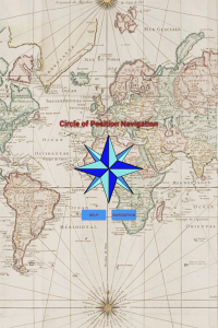
When the app is launched, an opening screen appears with the function name „Circle of Position Navigation“, which is shown in Figure 2.1. Circle of Position (COP) means an imaginary circular line on the globe from which the same star can be seen at the same altitude above the horizon at the same time and can therefore be a location. The following word navigation means that a location is calculated directly from one of the two intersection points of two overlapping spherical circles which result from observing two different stars or one star at different times. This is a significant difference to Saint Hilaire’s graphical altitude method, where the true circles of Position are replaced by straight line position lines in a location area to be estimated beforehand. This is also one of the reasons for the high calculation accuracy of the app. The HELP button can be used to call up a help file in which the individual functions are explained. After confirming a warning text, the Navigation button takes you to the main screen, which initially only displays the Earth globe. The warning text says:
Electronic data are to be used only as aids to navigation. They may only be used as a supplement to official sources and traditional navigation methods.
Safe navigation means constantly checking the different sources of information. If they do not match, the reason must be found.
In preparation for major trips, electronic chart representations must be checked against paper charts and manuals. For example with the PUB. xxx SAILING DIRECTIONS series.
A zoom option in electronic data is not suitable for identifying hazards.
Use this app at your own risk. The principles of good seamanship must be observed in all situations. The publisher of this app is not liable for any damage caused by improper use of the app.
2.1.1 Settings
Tapping the Settings icon opens the Settings bar, as shown in Figure 2.2. In order for the app to work properly, some basic settings must be made here. At the very top there is a button with which a TEST, MODE can be set. However, this is only available in the Pro version. In the line below, Approximate Latitude is used to ask what latitude you are currently at.
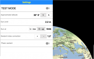
With this latitude you only have to indicate whether your current position is north or south of the current declination latitude. For example, if you enter 24° N, you select a sailing area that is north of all possible declination latitude. This will always calculate the northern intersection of the two intersecting circles. The entered latitude is immediately displayed as a grey latitude circle on the map, as can be seen in the following pictures.
The latitude set in the settings is later overwritten with the actual latitude after each new location calculation. In this way, the latitude at which you are currently located travels with you, so to speak.
The other specifications concern the sextant used and its use. The value Eye level indicates in metres how high the axis of the sextant’s telescope is above the waterline during an observation. Enter the distance between the telescope and the crest of the wave.
In the Basic version, the sun can only be put on the horizon with its lower limb on the horizon. The entry under Sun at cannot be changed in the Basic version. Under Sextant index correction not the index error of the sextant used is entered, but the value to correct it. This is then the negative value of the index error. The index error is easy to find out by first setting the degree arc and drum vernier to zero. If the horizon is observed in this setting, then two horizon lines lying on top of each other are seen in the case of an index error. These must now be brought into alignment with turn the drum. The angle subsequently read off is the index error. Its value is now entered with a reversed sign as the index correction.
The index error should be checked once a month for metal sextants. With plastic sextants, a correction is necessary immediately before or after an observation. The switch at Plastic sextant has the practical function that an index correction can be entered directly in the menu bar of Observations when using plastic sextants. With plastic sextants, the index error sometimes varies considerably between observation times due to different temperatures mostly through solar radiation, which means that index correction and observation must be successive activities.
With these basic settings, the app is ready to navigate. Tapping the icon with the sextant symbol opens the Observations menu, which can be seen in Figure 2.3. The necessary entries are now made here. For each observation, these are the date, which is, however, set automatically, the observation time to the second and the horizon distance of the sun measured with the sextant.
2.1.2 Observations
2.1.2.1 Circle of Position 1
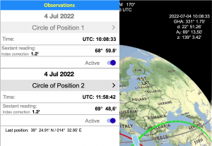
The use of the app will now be explained in detail using an example. During a voyage in the Mediterranean Sea, the first observation already entered in Figure 2.3 was made on 4 July 2022. The date is the date of the observation and is set by the device. It cannot be changed. In the block Circle of Position 1, the time to the second at which the sun touched the horizon in the telescope of the sextant was entered as Time. In the line Sextant reading below, the horizon distance read off the sextant is entered – without any correction. The data for Time is 10:08:33 UTC and for Sextant reading 68° 59.8′. The data has already been activated with the corresponding Active switch.
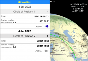
After tapping the map part visible on the right of the display or by tapping the sextant icon again, the menu disappears and the display shows only the map as shown in figure 2.4.From the date and time, the app calculates the Greenwich angle GHA with 331° 1.70′ and the declination δ with 22° 51.26′. The required sextant correction is calculated from the entries for eye level and index error stored in the settings as well as from the date and the measured altitude. The date is important for the so-called additional correction. Because the altitude of the sun is measured at its lower limb, but the center of the sun’s disc applies for the true altitude, the angle of half the sun’s diameter must be subtracted from the value read off the sextant. However, the diameter of the solar disk is not constant. In winter in the northern hemisphere, when the sun comes closest to the earth on its elliptical path, its diameter is optically somewhat larger, which must be corrected.
The under eye level entered value is used to correct the dip of the horizon. The higher you stand, the further you can see. Due to the curvature of the earth, you look then at a horizon that is farther and at the same time deeper, which increases the angle of elevation to the sun. Finally, a refraction error is calculated from the entered eye level, which is caused by light refraction in the atmosphere. If you also add this error to the sextant display, the observed altitude is AT = 69° 13.50′ (AT = True Altitude). This data is shown in the top right of the display for information only.
Once the data of a first observation is activated, it cannot be changed. If changes are necessary, e.g. due to a typing error, a restart must be carried out. For this purpose, the Active button is pressed and start deletes all previous entries. Afterwards, everything must be entered again.
2.1.2.2 Circle of Position 2
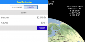
A second observation was made at 11:58:42 UTC, with the Sun placed over the horizon in the telescope at a sextant angle of 69° 48.6′. The observed time and the sextant reading are now entered in the block Circle of Position 2, as shown in Figure 2.5. After tap the activ switch, the app automatically opens the Dead Reckoning menu so that a change of location can be taken into account. This dead reckoning menu can be seen in picture 2.6.
Dead reckoning is necessary so that a change in location between observations can be taken into account in a location calculation. This change in location must be recorded by dead reckoning. In the basic version of the app, unfortunately, you have to dead reckoning „by foot“. For this purpose, the distance of the change of location over ground (DMG = Distance Made Good) and the average course over ground (CMG = Course Made Good) are estimated from notes to be made during the journey. The duration of speeds on the different courses as well as the drifting due to wind and current are always noted. In the old days, these things were noted down by the helmsman on a coupling board. From the entries, the captain or navigator then plotted the legs sailed on a chart and in this way determined a respective dead reckoning position (DR position) between the observations. The Pro version of the app contains a module for recording changes in location. The calculation of distance and course over ground „“by foot““ is therefore not necessary.
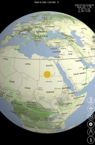
After entering the estimated sailing data of Distance = 12.5 NM and Course = 170°, these must be confirmed with ACCEPT. The position then calculated is shown on the lower left of the display as Last position. Since several observations can follow during the day, these are always displayed as the Last position. The position must always be entered from the first observation. The change in location must always be entered from the very first observation. In the Pro version, a DR position is additional given, which is made up of the last position and the data of the Dead Reckoning Module.
Alternatively, there is another possibility. By deactivating Circle of Position 1 (COP 1), the option to take over entered data from the last COP 2 observation is offered. This restart after any second observation offers the advantage that the estimation of a sailed route becomes easier, because the respective changes in location are then no longer so great. It is then only to enter the distances and courses over ground between each two observations.
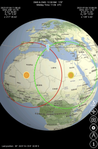
At the top left of the display, the Greenwich angle GHA with 358° 33.75′, the declination δ with 22° 50.85′ and the observed solar altitude AT with 70° 2.32′ are now shown. In addition, the azimuths z of both observations are now also calculated and indicated in the top right and left blocks respectively. After every second observation, the time of the ship’s noon is also shown at the top centre of the display. All data is for information purposes only and does not need to be used by the user.
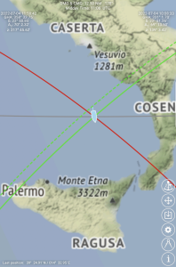
The electronic map can also be zoomed in the Basic version. However, this does not significant increase its resolution. Small islands, such as the volcanic island of Stromboli, which is currently being approached in Figure 2.8, are not displayed. A high resolution is only possible with the Pro version. However, the resolution in the Basic version is fully sufficient for an emergency navigation.
The zoomed graphic shows a total of four circles of Position. The green dashed circle is the circles of Position from the altitude of the first observation. The radius of this circles of Position changes due to the change of location during sailing. It is after that shown as a circle drawn through in green. It intersects with the circle of Position from a second observation, which is shown in red. The intersection is the position at the time of the second observation. The grey latitude circle is the new location latitude and replaces the latitude originally entered in the settings, which – as already mentioned – travels in this way.
So that the wrong intersection of the circles of position is not calculated the first time, it is important that the correct latitude is entered in the Settings at the beginning of a journey. Changing the entries in the Settings area is possible but only after deactivating the second observation. This does not delete any data.
It what if you are travelling on the other side of the world, perhaps even on the dateline? This is no problem either. After the date of the following day has been entered, the time of day of the second observation is before the time of day of the first observation, but a correct position is still calculated.
2.1.3 Until then
Astronavigation still has something romantic about it. Even if the many displays and detailed graphics are not needed at all, they were nevertheless made to clearly emphasise a difference to satellite navigation. Anyone who has ever attended a course on astronomical navigation can certainly still remember one or two of the terms.
If someone really does have to navigate astronomically after an incident , this app makes it very easy. The three entries in the settings should be ever made before a journey and should be never a problem. It is important to enter the approximate latitude right. Otherwise it can happen that not the northern, but the alternatively possible southern position is calculated. Under stress, one does not immediately understand how this can be corrected, although this is also quite simple.
A first observation can be made as soon as the sun can be seen as clearly as possible and is no longer too low in the sky. Altitudes below 25 degrees should be avoided if possible. A stopwatch should be used to accurately determine the observation time. This can also be the one in a mobile phone. This is started at a full minute of the UTC world time. It is stopped when the altitude of the sun is determined, if possible by calling out to a second person. The start time of the stopwatch and its running time are then added together to give the observation time. Entering this time and the sextant reading under Circle of Position 1 is all the work to be done after the first observation.
The second observation is then to be made in the same way. Normally, however, there should be a minimum of two hours in between so that the circles of Position intersect at a reasonably dull angle. The graphs produced allow a good assessment in this respect. Orientation is also possible by the difference in the azimuths. After activating the second observation and entering the sailed change of location, the calculated position is output immediately. Activating a second observation also provides ever the ship’s noon.
The app is practically self-explanatory. Its use requires no knowledge of mathematics or astronomy. A frequently asked question in astronavigation is accuracy. Except for the fact that the Earth is not a sphere but a somewhat flattened ellipsoid, the Gaussian mathematics used is accurate. The ellipsoid shape causes only minor errors. The biggest errors are caused by inaccurate measurements of altitude and time. Even experienced sextant users on a non-swaying ship can only achieve location deviations that are greater than one or two miles.
Application errors should not be underestimated. When sextants were still used for navigation all over the world, seafarers knew that sun elevations below 15° and above 80° were taboo. In addition, position lines should never cross at angles below 30°. This still applies to some extent in postmodern astronavigation. The altitude limit of 80° has been dropped, but the lower limit must also be observed here, because it is set by the composition of the Earth’s atmosphere. With the intersecting angles, one can also allow somewhat less, because position lines no longer have to be drawn. How far you can go, however, depends very much on the accuracy of the height measurements.
In the basic version of the app, the solar ephemeris is calculated directly with the help of a small module. This chosen method of calculation is not quite as accurate as in the Pro version. There, the ephemerides are not calculated, but are provided by a database.
The calculations of the Greenwich angle and declination are not as complicated as one might think. As a result of the direct calculation, location deviations of 0.3 NM on average occur. These can also be up to 0.5 NM at times. Since a total error is geometrically composed of individual errors, this hardly plays a role in the overall evaluation. We will try to recreate this once.
If erroneous measurements cause a position deviation of, for example, 2 NM and the mathematics with erroneous ephemerides is wrong by up to 0.5 NM, then according to the law of error propagation these two errors are to be regarded as the cathets of a right-angled triangle – and the total error is the hypotenuse of the triangle. This results in the following according to Pythagoras:
Error progression:
![\[\text{total error}=\sqrt{\text{measurement error}^2+\text{calculation error}^2}\]](https://astro-navigation.com/wp-content/ql-cache/quicklatex.com-ae1a4bbd2e586e23a0eaf3d20e4e2431_l3.png "Rendered by QuickLaTeX.com")
![\[F_{tot}=\sqrt{2^2+0,5^2}\text\;{NM}=\underline{\underline{2,06\,NM}}\]](https://astro-navigation.com/wp-content/ql-cache/quicklatex.com-958e6bc66fef9c09da0ea285d37ceb35_l3.png "Rendered by QuickLaTeX.com")
A position deviation of two nautical miles caused by measurement deviations can only be worsened by 0.06 nautical miles due to a mathematical miscalculation of 0.5 nautical miles. That is less than 5%.
2.2 Sun Navigation Pro
The Professional version differs from the Basic version by the ten additional functions mentioned at the beginning, which are explained below.
2.2.1 Second system for arbitrary inputs
This is a completely independent second navigation system that can also be operated in parallel to a currently active navigation. It works with its own basic settings, which are assigned in the Settings menu. If the switch is set to TEST MODE = ON, the basic settings for the second system are entered. If this switch is set to OFF, all entries apply to the default navigation system. To identify the second system, TEST MODE is written in yellow at the bottom of the display.
For the simulation of changes of location, only the function Specify is available in TEST MODE, i.e. the course and distance of a change of location between the observations must be specified.
In this second system, any specifications for date, time and altitude can be made. The user is immediately presented with the results of his entries in graphics and calculated figures on the display. In this way, a wide variety of scenarios can be simulated, displayed and examined without any effort, depending on the seasons and sea areas. The second system is also an ideal tool for learning to understand navigation with the sun and the nature of astronavigation in general in a vivid way.
It is easy to understand, for example, that major errors can occur if the times between observations are too short. It is also easy to see how navigation should be carried out in order to obtain useful results with the shortest possible times between observations. For example, it can also be shown that the noon latitude can serve very well when sailing close to the declination latitude.
The TEST MODE can also be used to optimize an active navigation that is currently running. With a copied first observation, it is easy to find out whether a noon latitude would be more favorable as a second observation or at what time a second observation promises an optimal crossing angle. The TEST MODE accepts any input, but only calculates a position if the input allows it.
2.2.2 Use of the noon latitude
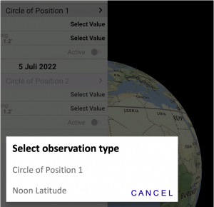
The noon latitude is probably the most frequently measured position circle in the history of maritime navigation. Columbus used the noon latitude also to find his way back to Europe. In the Pro version, the app also allows the use of the noon latitude. Its function is activated by tapping the line Circle of Position 1 (or 2) in the Observation menu. This opens a selection window in which the noon latitude function Noon latitude is then selected, as shown in Figure 2.9.
The measurement of the noon latitude does not have to be accurate to the second, because the sun apparently remains at the same altitude for minutes during its culmination. It is only important to know the approximate time of culmination long before that, so that you do not have to expose yourself to sunlight for too long to take a measurement. The time of ship’s noon is shown at the top center of the display after two consecutive altitude measurements (COP 1 and COP 2). Both observations must therefore be made during the morning. The indicated time of the ship’s noon will be accurate enough if the intermediate time is at least one hour.
A few minutes before the indicated noon time, start finding the culmination time of the sun by measuring its altitude about every two minutes until a decrease in altitude can be detected. The greatest of the altitudes measured is the sextant angle of the culmination height. This is then entered under sextant reading.
It is important to indicate whether the sun was observed to the north or south during its culmination. If the sun is very high, it is possible that altitudes of more than 90° are observed. In this case, the sun was observed in the wrong direction. A westerly or easterly course can be somewhat helpful in observing the correct bearing. You can also subtract the amount exceeding 90° from 90°. If you measure 95°, then the altitude is actually 85°.
If sailing in latitudes that differ little from the declination latitude, then using the noon latitude can be very advantageous. If the second observation was a noon latitude, this can be adopted as the first observation for future observations. To do this, tap the Active button in the block Circle of Position 1. A selection window opens, similar to the one shown in Figure 2.9. Here you can choose between a restart or taking over the data from Circle of Position 2. The dead reckoning module also starts again from the beginning after such a takeover, thus deleting all data saved so far.
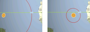
Figure 2.10 shows an afternoon navigation near the declination using a previously observed noon latitude. This always gives good crossing angles throughout the rest of the day and therefore accurate location results.
When using the noon latitude in TEST MODE, can do any culmination times are entered which cannot occur in practice. This leads to location results that are not quite correct, because the noon latitude circle is calculated on the basis of the observed altitude and declination. However, because all time entries are permitted here, the declination calculated from this and thus the calculated position could be incorrect.

 , the cathetus
  must not be longer than 10 minutes.
The app therefore performs a plausibility check, which is explained with the graphic in Figure 2.11. A culmination occurs when the position and image point of the sun are on the same meridian. In this case, the time Δt = 0, which is shown exaggeratedly large in the graphs. Furthermore, the zenith distance 90° – h is then equal to the difference .
In a right-angled spherical triangle, the cosine of the side opposite the right angle is equal to the product of the cosines of the other two sides. Thus the quotient of the cosines of the sides (90° – h) and  is equal to the cosine of the radian of the side Δt. If an angle of 2.5° is allowed for this, then you get exactly 10 minutes for Δt (15° = 1 h).
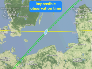
The app thus checks whether all data fit into this time window of Δt = 10 minutes, in which the culmination can only have been possible. If observation times beyond this are entered, an unfitting declination would be called up. This leads to the warning message Impossible observation time! in yellow letters, as shown in the adjacent Figure 2.12.
In normal navigation mode this should not happen, because the true time of the noon latitude observation is known and normally entered as read. Location errors as a result of incorrectly calculated declination due to grossly incorrect time information are therefore hardly possible.
2.2.3 Downloading high-resolution maps
Downloading high-resolution maps works best in a fast WLAN network without volume limits. After the download, the maps are available offline. All areas that were previously viewed online in high resolution are likewise available offline. However, these areas cannot be surrounded by a frame.
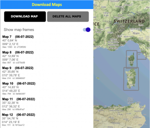
This is only possible with maps downloaded with DOWNLOAD MAP. The frames have the advantage that they can be used to point out smaller islands that could easily be overlooked with a coarser zoom. Downloading is very simple. After tapping the corresponding icon, the download menu opens with the DOWNLOAD MAP and DELETE ALL MAPS buttons. Below this is a button for switching map frames on and off. The maps that have already been downloaded are numbered consecutively.
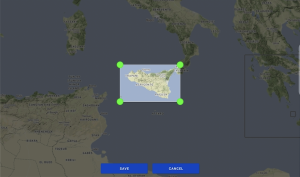
To download another map, first slide the intended sailing area into the display. After tapping the DOWNLOAD MAP button, a window with four green handles appears in the centre of the display on an otherwise darkened map. With these handles, the slide and zoom function, the area to be downloaded can now be framed and loaded with SAVE. Figures 2.13 and 2.14 illustrate the procedure.

If you tap on one of the lines of a loaded map shown in Figure 2.13, it is brought to the center of the display. By tapping the download icon at the bottom of the display, the bar with the map list disappears again. The maps can also be deleted individually. To do this, the corresponding map line is moved to the left, whereupon the red „Delete“ field appears on the right for confirmation.
Figure 2.15 demonstrates how far you can zoom into the downloaded map material. A coastline can thus be displayed precisely and a particular bay or marina can be targeted from a distance.
2.2.4 Dead Reckoning Module
Since only the sun is used as a navigation star and two observations of the sun at different times are necessary to calculate a position, the distance covered in the time between the observations and the average course followed must be calculated. This process is called dead reckoning. It is often used in abbreviated form, for example as DR position, DR latitude, etc. For dead reckoning, only the basic parameters of a movement are continuously recorded: the direction with a compass, the speed with a log and the time with a clock. In addition, the influences of wind and current have to be considered. Since the 15th century, this type of navigation has been considered an important method of orientation at sea. In earlier times, however, it was carried out graphically, because algebraically it would have become too demanding. The error of a carefully executed dead reckoning must not be greater than 5%.
If the Reckoning method is used, then the distance travelled through the water and the course travelled must be specified, taking into account the wind offset. If there is an ocean current, the direction and speed of the current can also be specified. Sea currents are provided by a current radar, for which, however, one must be online. If necessary, a friend back home can be asked for information via a satellite phone.
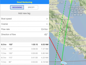
The app generates a so-called coupling board from the information, which is shown in the lower half on the left in figure 2.16. In this board, the speed of each leg is shown. For each leg, it shows the speed through the water, the course followed, the duration of the leg and the distance covered, taking into account a specified ocean current. A new leg is created as soon as there is a change in either the speed or the course or both. This happens after tacks, jibes, course corrections or sustained speed changes. The app must therefore be „fed“ after every sailing maneuver. Changes in the ocean-current conditions do not cause a new line in the coupling table. They are always included in the current leg as long as their sizes are visibly entered in the corresponding fields.
After each activation of a second observation (COP 2), the app accesses the current data of the Dead Reckoning module and calculates the position taking into account the change in location sailed. This position is indicated at the bottom left of the display as Last position. However, since dead reckoning continues, the dead reckoning location is listed as the DR position.
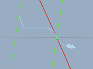
The results of the reckoning function are also displayed graphically on the map as a track in blue color, as shown in Figure 2.17. After each new location calculation, this track is continued as a dashed line. In addition, the DMG, CMG and VMG (Velocity Made Good) data, i.e. distance travelled over ground, course over ground and speed over ground, are constantly displayed in the mid at the top of the display. Tacks, jibes, changes in course and speed as well as currents are considered according to the entries made.
If Specify is selected, the app will ask for the DMG and CMG data each time a second observation is activated. The data from the time of the first observation must be entered here. In this case, dead reckoning must be carried out manually. Alternatively, every second observation can be taken over as the first observation and then only the changes in location in the time elapsed between the observations must always be entered.
2.2.5 Sun Almanac
For a classical position calculation according to Saint Hilaire’s intercept method, one always needed a nautical yearbook from which the position data of the Sun, its Greenwich angle and its declination, could be taken for a given observation time.
This was always a time-consuming procedure. The angles of the full hour or part thereof was taken from the day’s page. For the minutes and seconds, there were the pages with the switchboards at the end of the book, with the help of which an increment was calculated and then both had to be added. This is exactly how it is still taught today in the astronavigation courses at sailing schools.
The calculation of these data, the so-called ephemerides of the sun, is actually quite simple if Johannes Kepler’s two-mass system is used. Nowadays, this calculation is done by any smartphone in milliseconds. Although the values only have an accuracy of 0.5′ on average, calculated location deviations are perhaps only 0.3 nautical miles worse than with ephemerides calculated to 0.1′. This is because the unavoidable errors in the measurement of horizon distance and time are much greater and calculation errors have reduced effects as a result. In the basic version, the ephemeris calculation takes place directly in the mobile device.
More accurate results are obtained by taking into account the masses of the Moon and the major planets. The Moon and the Earth form a mass system with a center of mass that lies in the Earth’s interior, but no longer in the center of the Earth. Thus one must see that it is not the center of the Earth but this center of mass that orbits the Sun. The moon orbits the earth once in 29.5 days, which means that the earth changes its speed in this rhythm from the point of view of the sun on its orbit. It seems to travel two weeks faster and two weeks slower at times, which then leads to the deviations.
The positions of the Sun’s zenith point, the solar ephemerides, are therefore influenced by the Moon’s position. Another dependency is due to the mass attraction of the large planets. All this can no longer be easily calculated by a mobile phone chip. The ephemerides in the Professional Version have therefore been calculated externally and are kept in a database by the app. This database contains the predicted data for the Greenwich angle and the declination of the solar image point with an accuracy of 0.1′ until 31 December 2040.
2.2.6 Observation over several days
The maximum time between a first and a last second observation was limited in the basic version to twelve hours for one day. After very short and very long intermediate times, the circles of position only intersect at very acute angles, which means that inaccuracies in the altitude and time measurements lead to greater errors. In any case, no position can be determined on the following night. Only on the following day would observations be possible again, where the circles of Position intersect at obtuse angles. However, the reckoning result could then cause a somewhat larger position error. In short, this means that one should avoid allowing days between the first and the last second observation if possible.
Even though it is very unlikely, the weather might force you to do so. For this reason, the Pro version offers the possibility of making continuous observations over a maximum of three days.
2.2.7 Observing the Sun at the Upper Limb
Normally, in the telescope of the sextant, the sun is put with its lower limb on the horizon. However, it can happen that clouds have already covered the lower limb of the sun and are increasing, so that only a quick observation of the sun at its upper limb is possible. For this purpose, the last second observation must be deactivated and a switch from Sun at lower limb to upper limb must be made in the settings. Since all subsequent observations would also be affected by this switch, do not forget to set the usual observation mode again.
2.2.8 Display of the DR Position
When using the reckoning function, a DR position is calculated continuously from the first observation. This calculation is terminated when a restart is initiated after deactivating COP 1 or when a take-over of data from a second observation takes place. After a position calculation, which was done considering the sailed distance, the position of the vessel is further extrapolated as DR position from the entered data. This is comparable to the position indication when driving a car through a long tunnel, where the position is no longer determined from satellite signals, but from wheel roll.
2.2.9 Great circle calculation: distance and course to a destination
Sometimes you want to know how far it is from your position to a destination. This function can be called up via the icon with the compass symbol. The shortest distance on a spherical surface is calculated. Even if you want to go to a distant destination at the same latitude, the path along the same latitude is not the shortest path – unless you are on the equator. The shortest path is always the bearing direction or, in other words, the orthodrome. That is the theory. However, it is more important to take this into account when sailing with motorboats than when sailing with sailboats.
Why can’t you actually take a bearing along a latitude? Just imagine being on a latitude that is only a few metres from the North Pole. Attempting to take a bearing along this circle of latitude fails because it is a circle that lies in front of you. From one point to a second point on the same or a different circle of latitude, one can only take a bearing as the crow flies, and that is the orthodrome, which always follows the spherical curvature of the earth’s surface and is thus the shortest connection on a spherical surface.
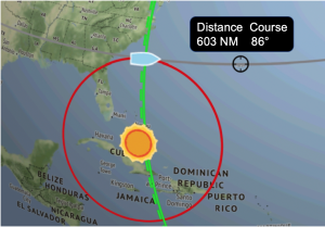
Based on this knowledge, the distance between two positions on the earth’s surface must be calculated with the help of spherical trigonometry. In order to be able to cover this distance optimally, a so-called initial course must also be calculated. This should then be recalculated from time to time, especially for very long journeys. Figure 2.18 shows an example of a distance measurement from one’s own position to Bermuda, where the island and one’s own position lie on almost the same latitude. The initial course calculated was not 90° but 86°. The great circle calculation is always only available after a second observation – i.e. from an established position.
2.3 By the way
The app presented here is of course also available in the App Store as an iOS version, but there only in a professional version. Operation and functionality are identical to the Android version.
If you want to use the app as an emergency system, you should remember to have a solar charger on board as well as a sextant. A power failure due to a defective battery has already happened to me. After that, nothing works any more. If you then have to spend many days at sea until you reach the next coast, the mobile phone battery is empty.
Speaking of smartphones, they can also display a position! Yes, that’s true, but without an additional paper sea chart on which you can locate and draw the position displayed, you’re pretty helpless with just these numbers. Google Maps is only available near the coast. So the apps „Sun Navigation“ and „Circle of Position Navigation“ are the better helpers in a pinch, even if you need a sextant. In any case, a sextant on board provides additional safety, even for coastal navigation.
For all those who like to navigate with the sextant, it would also be nice to have an astro module in the chart plotter. That would be quite easy to create. The other articles on this page provide the necessary theoretical and mathematical basics for this. But this is something the industry should think about, as already mentioned.